ArcadeMicroColourEnglish: Difference between revisions
ArneRossius (talk | contribs) No edit summary |
ArneRossius (talk | contribs) No edit summary |
||
| (4 intermediate revisions by the same user not shown) | |||
| Line 16: | Line 16: | ||
== Hardware == | == Hardware == | ||
The LED matrix is made up from three times 26 columns (for red, green and blue) and 20 rows. The multiplexing | The LED matrix is made up from three times 26 columns (for red, green and blue) and 20 rows. The multiplexing is going across the rows from bottom to top, so only one line is lit up at a time. The refresh rate is 100 Hz for the lowest grayscale and increases for brighter LEDs. The electronics must be supplied from a 5 V power supply capable of supplying at least 0.9 A. | ||
This project uses two PCBs: one containing only the LEDs and one containing the controlling circuitry. The two PCBs are connected through the board-to-board connectors X1 to X5. | This project uses two PCBs: one containing only the LEDs and one containing the controlling circuitry. The two PCBs are connected through the board-to-board connectors X1 to X5. | ||
* [[:Media:AMC-rev1.0-instructions.pdf|Construction kit instructions Rev. 1]] | On the controller board Rev. 1.0 (and Rev. 1.0b), the green and blue connections are swapped for one of the LED columns. For this reason, a fix must be enabled in the BlinkenPlus software. | ||
* [[:Media:AMC-rev1.0-instructions.pdf|Construction kit instructions Rev. 1.0]] | |||
* [[:Media:AMC-rev1.1-instructions.pdf|Construction kit instructions Rev. 1.1]] | * [[:Media:AMC-rev1.1-instructions.pdf|Construction kit instructions Rev. 1.1]] | ||
* [[:Media:AMC-rev1.2-instructions.pdf|Construction kit instructions Rev. 1.2]] | * [[:Media:AMC-rev1.2-instructions.pdf|Construction kit instructions Rev. 1.2]] | ||
| Line 26: | Line 28: | ||
=== Controller Board === | === Controller Board === | ||
* [[:Image:AMC_Controller_rev1.0_schematic.png|Schematic Rev. 1]] (PNG) | * [[:Image:AMC_Controller_rev1.0_schematic.png|Schematic Rev. 1.0]] (PNG) | ||
* [[:Media:AMC_Controller_rev1.0.sch|Schematic Rev. 1]] (Eagle 4.x) | * [[:Media:AMC_Controller_rev1.0.sch|Schematic Rev. 1.0]] (Eagle 4.x) | ||
* [[:Media:AMC_Controller_rev1.0.brd|PCB layout Rev. 1]] (Eagle 4.x) | * [[:Media:AMC_Controller_rev1.0.brd|PCB layout Rev. 1.0]] (Eagle 4.x) | ||
* [[:Media:AMC_Controller_rev1.0b.brd|PCB layout Rev. 1.0b]] (Eagle 4.x, only silkscreen changes) | * [[:Media:AMC_Controller_rev1.0b.brd|PCB layout Rev. 1.0b]] (Eagle 4.x, only silkscreen changes) | ||
=== LED Board === | === LED Board === | ||
* [[:Image:AMC_LED_rev1.0_schematic.png|Schematic Rev. 1]] (PNG) | * [[:Image:AMC_LED_rev1.0_schematic.png|Schematic Rev. 1.0]] (PNG) | ||
* [[:Media:AMC_LED_rev1.0.sch|Schematic Rev. 1]] (Eagle 4.x) | * [[:Media:AMC_LED_rev1.0.sch|Schematic Rev. 1.0]] (Eagle 4.x) | ||
* [[:Media:AMC_LED_rev1.0.brd|PCB layout Rev. 1]] (Eagle 4.x) | * [[:Media:AMC_LED_rev1.0.brd|PCB layout Rev. 1.0]] (Eagle 4.x) | ||
== Software == | == Software == | ||
| Line 43: | Line 45: | ||
== Photos == | == Photos == | ||
More photos available at http://arne.blinkenarea.org/ArcadeMicro%20Colour/. | More photos available at http://arne.blinkenarea.org/ArcadeMicro%20Colour/gallery.htm. | ||
[[Category:Projects]] | [[Category:Projects]] | ||
[[Category:BlinkenPlusProjects]] | [[Category:BlinkenPlusProjects]] | ||
Latest revision as of 13:27, 7 August 2016
| project overview | |

| |
| Year | 2013 |
| Number of pixels | 520 |
| Grayscales / Colors | RGB, 83 = 512 colours |
| Illuminant | SMD LEDs |
| Power input | 4.5 W |
| Contact person | Arne Rossius |
| Project website | |
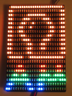
ArcadeMicro Colour is a project with the same resolution as BlinkenLights ARCADE (26x20 pixels, pixel aspect ratio 1:2) with RGB LEDs in the same size as the monochrome ArcadeMicro.
Hardware
The LED matrix is made up from three times 26 columns (for red, green and blue) and 20 rows. The multiplexing is going across the rows from bottom to top, so only one line is lit up at a time. The refresh rate is 100 Hz for the lowest grayscale and increases for brighter LEDs. The electronics must be supplied from a 5 V power supply capable of supplying at least 0.9 A.
This project uses two PCBs: one containing only the LEDs and one containing the controlling circuitry. The two PCBs are connected through the board-to-board connectors X1 to X5.
On the controller board Rev. 1.0 (and Rev. 1.0b), the green and blue connections are swapped for one of the LED columns. For this reason, a fix must be enabled in the BlinkenPlus software.
- Construction kit instructions Rev. 1.0
- Construction kit instructions Rev. 1.1
- Construction kit instructions Rev. 1.2
Controller Board
- Schematic Rev. 1.0 (PNG)
- Schematic Rev. 1.0 (Eagle 4.x)
- PCB layout Rev. 1.0 (Eagle 4.x)
- PCB layout Rev. 1.0b (Eagle 4.x, only silkscreen changes)
LED Board
- Schematic Rev. 1.0 (PNG)
- Schematic Rev. 1.0 (Eagle 4.x)
- PCB layout Rev. 1.0 (Eagle 4.x)
Software
This project uses the BlinkenPlus firmware.
Photos
More photos available at http://arne.blinkenarea.org/ArcadeMicro%20Colour/gallery.htm.