TicTacLightsColourEnglish: Difference between revisions
ArneRossius (talk | contribs) No edit summary |
ArneRossius (talk | contribs) No edit summary |
||
| (One intermediate revision by the same user not shown) | |||
| Line 26: | Line 26: | ||
The 3.3 V supply for the SD card is generated by a linear regulator. The maximum current draw of the circuit (all LEDs white at maximum brightness) is approx. 250 mA, not including the current consumption of the SD card (if inserted). | The 3.3 V supply for the SD card is generated by a linear regulator. The maximum current draw of the circuit (all LEDs white at maximum brightness) is approx. 250 mA, not including the current consumption of the SD card (if inserted). | ||
From revision 2.0 onward, there is a CH340G USB to UART converter IC on the board. This means the USB port can be used for streaming [[MCUFEnglish|MCUF]] frames in addition to supplying power. | From revision 2.0 onward, there is a CH340G USB to UART converter IC on the board. This means the USB port can be used for streaming [[MCUFEnglish|MCUF]] frames in addition to supplying power. It is also possible to use CH340C, in which case C11, C12 and Q2 must be omitted. | ||
=== Rev. 2.0 === | === Rev. 2.0 === | ||
| Line 32: | Line 32: | ||
* [[:Image:TLC-rev2.png|Schematic]] (PNG) | * [[:Image:TLC-rev2.png|Schematic]] (PNG) | ||
* [[Media:TLC-gerber-rev2.0.zip|PCB Gerber files]] including solder paste mask files | * [[Media:TLC-gerber-rev2.0.zip|PCB Gerber files]] including solder paste mask files | ||
* [[Media:TLC-instructions-rev2. | * [[Media:TLC-instructions-rev2.5.pdf|Construction kit instructions Rev. 2.5]] | ||
* [http://www.wch.cn/download/CH341SER_EXE.html Windows driver for CH340G] | * [http://www.wch.cn/download/CH341SER_EXE.html Windows driver for CH340G] | ||
Latest revision as of 22:41, 16 July 2021
| project overview | |

| |
| Year | 2014 |
| Number of pixels | 144 |
| Grayscales / Colors | 512 colours |
| Illuminant | SMD LEDs (size 0805) |
| Power input | 1.25 W |
| Contact person | Arne Rossius |
| Project website | |
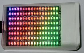
The TicTacLights Colour is the RGB version of the TicTacLights, a very small BlinkenLights clone that fits inside a small TicTac box. Unlike the monochrome version, the TicTacLights Colour requires a 5 V power supply, e.g. a USB port. The PCB has a Mini-USB-B connector and internal pads for a possible battery supply (e.g. a lithium-ion battery with a switching converter for constant 5 V).
This project uses the BlinkenPlus firmware on an ATmega162 controller. The PCB has pads for a Micro-SD card slot and solder pads for a serial port (5 V logic level, RS232-compatible with external level converter, e.g. MAX232).
IMPORTANT: 32C2 Kits
Unfortunately, the kits sold during 32C3 contain a faulty circuit board. If you bought a kit during 32C3, please contact me at arne@blinkenarea.org for a replacement.
Hardware
The hardware is very similar to the Blinkström Colour, the only difference is that the rows are driven directly from the controller rather than through MOSFETs. This is possible because the TicTacLights Colour uses a lower LED current than the Blinkström Colour.
The 3.3 V supply for the SD card is generated by a linear regulator. The maximum current draw of the circuit (all LEDs white at maximum brightness) is approx. 250 mA, not including the current consumption of the SD card (if inserted).
From revision 2.0 onward, there is a CH340G USB to UART converter IC on the board. This means the USB port can be used for streaming MCUF frames in addition to supplying power. It is also possible to use CH340C, in which case C11, C12 and Q2 must be omitted.
Rev. 2.0
- Schematic (PNG)
- PCB Gerber files including solder paste mask files
- Construction kit instructions Rev. 2.5
- Windows driver for CH340G