BulbEnglish
| project overview | |

| |
| Year | 2011 |
| Number of pixels | 42 |
| Grayscales / Colors | 16 grayscales (gamma 2.0) |
| Illuminant | SMD LEDs |
| Power input | 120mW |
| Contact person | Stefan Schuermans |
| Project website | |
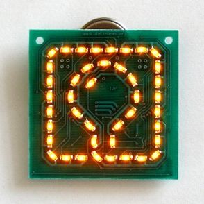
BlinkenArea ultimate logo board - "bulb" for short - is a small circuit board of 5x5cm showing the BlinkenArea logo with 42 LEDs. The orange LEDs display several animations using 16 brightness levels (gamma = 2.0). The board is powered by a single CR2032 button cell.
This project is an extension of AntiKippenLights-Mini (which is a shrinked remade of AntiKippenLights).
Downloads
- [[::Image:Bulb-electrics-1.0.0_2011-07-02.tar.bz2|electrics 1.0.0 (schematic, part list and layout)]]
- [[::Image:Bulb-firmware-1.0.0_2011-07-30.tar.bz2|firmware 1.0.0 (source code)]]
- [[::Image:Bulb-prog-1.0.0_2011-07-30.zip|firmware 1.0.0 (hex code)]]
Images
Instructions for assembling the kit
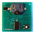
1) download the "electrics" package and unpack it 2) look at page 12 of "bulb.pcb.pdf" 3) solder the LEDs as seen in the PDF (the black dots next to the LEDs in the PDF indicate where the green dots on the actual LEDs have to be) 4) look at page 13 of "bulb.pcb.pdf" 5) solder the resistor (tiny, dark, with "1002" printed on it) to the position R1 (polarity does not mater) 6) solder the capacitor (tiny, brown, nothing printed on it) to the position C1 (polarity does not matter) 7) solder the FET (small black, 8 pins) to the position T1 (the dot on the actual part goes to the side with the half circle in the PDF) 8) solder the microcontroller (bigger, black, 20 pins) to the position IC1 (the dot on the actual part goes to the side with the half circle in the PDF) 9) solder the button to the position S1 (polarity does not matter) 10) solder the battery holder to the position B1 11) insert the battery 12) program the microcontroller via the debug pads DBG1 - or ask Stefan from BlinkenArea to do that


