SimpleClockEnglish: Difference between revisions
ArneRossius (talk | contribs) No edit summary |
ArneRossius (talk | contribs) No edit summary |
||
| Line 12: | Line 12: | ||
}} | }} | ||
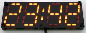
The SimpleClock is a 4-digit digital clock using an absolute minimum of components. The display consists of 58 red LEDs (2 per segment), connected to an 8-pin ATtiny13 microcontroller | The SimpleClock is a 4-digit digital clock using an absolute minimum of components. The display consists of 58 red LEDs (2 per segment), connected to an 8-pin ATtiny13 microcontroller. The mains frequency is used as a time base, hence an AC-AC adapter (transformer) is required to power the clock. If a DC source is used, the time will stand still and the colon won't flash. | ||
The | == Hardware == | ||
The LEDs are driven using a technique called "CharliePlexing Plus", explained in [https://cpldcpu.wordpress.com/2015/05/24/plexingplus/ Tim's Blog]. For the LEDs connected between an I/O pin and GND or Vcc, two LEDs must be connected in series for this technique to work. For the LEDs between I/Os, two LEDs are connected in parallel (and another two anti-parallel) to get 2 LEDs for every segment. The internal resistance of the microcontroller's output pins is used for current limiting. | |||
Revision as of 15:41, 27 December 2018
| project overview | |

| |
| Year | 2018 |
| Number of pixels | 58 |
| Grayscales / Colors | 2 |
| Illuminant | rectangular LEDs |
| Power input | |
| Contact person | Arne Rossius |
| Project website | |
The SimpleClock is a 4-digit digital clock using an absolute minimum of components. The display consists of 58 red LEDs (2 per segment), connected to an 8-pin ATtiny13 microcontroller. The mains frequency is used as a time base, hence an AC-AC adapter (transformer) is required to power the clock. If a DC source is used, the time will stand still and the colon won't flash.
Hardware
The LEDs are driven using a technique called "CharliePlexing Plus", explained in Tim's Blog. For the LEDs connected between an I/O pin and GND or Vcc, two LEDs must be connected in series for this technique to work. For the LEDs between I/Os, two LEDs are connected in parallel (and another two anti-parallel) to get 2 LEDs for every segment. The internal resistance of the microcontroller's output pins is used for current limiting.