TicTacLightsEnglish: Difference between revisions
ArneRossius (talk | contribs) (Created page with "Coming soon ...") |
ArneRossius (talk | contribs) No edit summary |
||
| Line 1: | Line 1: | ||
__NOEDITSECTION__ | |||
{{InfoboxEnglish | |||
|Name=TicTacLights | |||
|Bild=Tictaclights-operating-crop.jpg | |||
|Jahr= 2012 | |||
|Pixel= 144 | |||
|Farben=8 Grayscales | |||
|Leuchtmittel=SMD LEDs (size 0805) | |||
|Leistung= | |||
|Kontakt=[[User:ArneRossius|Arne Rossius]] | |||
|Webseite= | |||
}} | |||
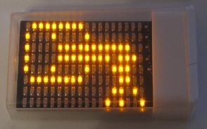
The '''TicTacLights''' is a very small [[BlinkenLights]] clone which fits inside a small TicTac box. It is powered by a CR2032 button cell battery. Battery life is only about 30 minutes, alternatively a lithium-polymer battery with an additional voltage regulator can be used. | |||
This project uses the [[BlinkenPlusEnglish|BlinkenPlus]] firmware on an ATmega8515 controller. The PCB has pads for a Micro-SD card slot and solder pads for a serial port (with external level converter, e.g. MAX3232). | |||
== Hardware == | |||
The hardware is kept very simple because there isn't a lot of space on the PCB. The columns are directly connected to the controller's outputs, so large currents are not possible. Due to the high internal resistance of the button cell battery, the voltage drops quickly, causing the controller and the SD card to operate outside of their specifications (which requires a minimum voltage of 2.7 V). | |||
* [[:Image:Tictaclights-rev1.png|Schematic]] | |||
* [[Media:Tictaclights-rev1.sch|Schematic]] (Eagle file, version 4.16) | |||
* [[Media:Tictaclights-rev1.brd|PCB Layout]] (Eagle file, version 4.16) | |||
* [[Media:Tictaclights-instructions-rev1.pdf|Construction kit instructions]] | |||
Revision as of 18:48, 27 December 2012
| project overview | |

| |
| Year | 2012 |
| Number of pixels | 144 |
| Grayscales / Colors | 8 Grayscales |
| Illuminant | SMD LEDs (size 0805) |
| Power input | |
| Contact person | Arne Rossius |
| Project website | |
The TicTacLights is a very small BlinkenLights clone which fits inside a small TicTac box. It is powered by a CR2032 button cell battery. Battery life is only about 30 minutes, alternatively a lithium-polymer battery with an additional voltage regulator can be used.
This project uses the BlinkenPlus firmware on an ATmega8515 controller. The PCB has pads for a Micro-SD card slot and solder pads for a serial port (with external level converter, e.g. MAX3232).
Hardware
The hardware is kept very simple because there isn't a lot of space on the PCB. The columns are directly connected to the controller's outputs, so large currents are not possible. Due to the high internal resistance of the button cell battery, the voltage drops quickly, causing the controller and the SD card to operate outside of their specifications (which requires a minimum voltage of 2.7 V).
- Schematic
- Schematic (Eagle file, version 4.16)
- PCB Layout (Eagle file, version 4.16)
- Construction kit instructions