L8CubeEnglish: Difference between revisions
(New page: __NOEDITSECTION__ {{InfoboxEnglish |Jahr= |Pixel= 512 (8x8x8) |Leistung= |Kontakt= Sebastian Müller |Webseite= https://www.chaostreff-mannheim.de/wiki/Lightcube...) |
ArneRossius (talk | contribs) No edit summary |
||
| Line 1: | Line 1: | ||
__NOEDITSECTION__ | __NOEDITSECTION__ | ||
{{InfoboxEnglish | {{InfoboxEnglish | ||
|Name=L8Cube | |||
|Bild=L8cube.jpg | |||
|Jahr= | |Jahr= | ||
|Pixel= 512 (8x8x8) | |Pixel= 512 (8x8x8) | ||
| Line 7: | Line 9: | ||
|Webseite= https://www.chaostreff-mannheim.de/wiki/Lightcube | |Webseite= https://www.chaostreff-mannheim.de/wiki/Lightcube | ||
}} | }} | ||
== Idea == | == Idea == | ||
Latest revision as of 00:22, 13 June 2010
| project overview | |

| |
| Year | |
| Number of pixels | 512 (8x8x8) |
| Grayscales / Colors | |
| Illuminant | |
| Power input | |
| Contact person | Sebastian Müller |
| Project website | https://www.chaostreff-mannheim.de/wiki/Lightcube |
Idea
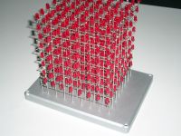
This project deals with building-up a 3D-Lightcube (LED Cube). The idea derives from the LED-Cube which was geared to James Clar's Version. My contruction should contain an arrangement of 8x8x8 LEDs.
The Cube is controlled by a AVR Mega32 over three ports with eight pins each. The single ports are responsible for the different axis of the coordinate system (porta = x / portb = y / portc = z).
In principle, the cube is a pure gadget but offers a wide range of capabilities. Display amplitudes to visualise audio singnals, a ticker or 3D games like Pong and Snake are supposable.
Connexion Scheme
- yellow = power supply / earth
- grey = supply
- purple = wire to the port of the microcontroller
- blue triangles = transistors
- red shells = LEDs
This picture reveals the operating mode of the circuit. The current flows over the yellow wire and the transistors decide which of the eight sections are energised and therewith, the 64 LEDs, too. To beware that all LEDs glow, the earth is taken by eight passages from the transistors which are connected in parallel. In the end, the last coordinate is defined and the connected wire gets contact with the earth.
You see, I am not an electrician engineer and had a lot of help from Pensoffsky to realise this project. Special thanks are delivered on this way. :-)
Components
- LED cube
- 8x8x8 = 512 diodes
- silver wire, 1mm (about 27m)
- case about 20cm x 15cm
- Circuit board
- 8x8 + 8 + 8 = 80 transistors
- copper wire, 0,1mm (about 1m)
- silver wire, 1mm (about 1,5m)
- Microcontroler
- ATMega AVR-RISC controller
- RS232 Driver
- Standardquarz 16 MHz
Pictures, code for download and always up-to-date information are available on the project website.
