AntiKippenLights: Difference between revisions
From BlinkenArea Wiki
No edit summary |
ArneRossius (talk | contribs) No edit summary |
||
| (8 intermediate revisions by 3 users not shown) | |||
| Line 1: | Line 1: | ||
__NOEDITSECTION__ | __NOEDITSECTION__ | ||
{{Infobox | |||
|Name=AntiKippenLights | |||
|Bild=Antikippenlights-02.jpg | |||
|Jahr= 2004 | |||
|Pixel= 18 | |||
|Farben= 64 Graustufen | |||
|Leuchtmittel= low current LED | |||
|Leistung= 270mW | |||
|Kontakt= [[User:StefanSchuermans|Stefan Schürmans]] | |||
|Webseite= - | |||
}} | |||
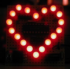
AntiKippenLights wurde vor dem 21C3 als Weiterentwicklung des KippenLights von [[User:StefanSchuermans|Stefan Schürmans]] gebaut. Das AntiKippenLights (auch als KippenLightsSpezial bekannt) enthält einen PIC-Microcontroller, der die LEDs einzeln ansteuern kann und somit mehrere verschiedene Blinkeffekte (teilweise mit Graustufen) auf dem AntiKippenLights abspielen kann. Die Reihenfolge der Animationen ist zufällig und wird durch den Elektrosmog an der Antenne bestimmt. ;-) | |||
=== Schaltung === | === Schaltung === | ||
| Line 10: | Line 20: | ||
Hinweis: bitte unbedingt Low-Current-LEDs verwenden! | Hinweis: bitte unbedingt Low-Current-LEDs verwenden! | ||
* [ | * [[:Image:Antikippenlights-01.brd|Eagle-Format]] | ||
* [ | * [[:Image:Antikippenlights-06.png|PNG-Grafik]] | ||
==== Stückliste (mit Reichelt-Bestellnummern) ==== | ==== Stückliste (mit Reichelt-Bestellnummern) ==== | ||
| Line 30: | Line 40: | ||
| 2 || Kondensator 22pF || KERKO 22P | | 2 || Kondensator 22pF || KERKO 22P | ||
|- | |- | ||
| 1 || | | 1 || Quartz 4MHz || 4,0000-HC49U-S | ||
|- | |- | ||
| 1 || Keramik-Resonator 4 MHz* || CST 4,00 | | 1 || Keramik-Resonator 4 MHz* || CST 4,00 | ||
| Line 46: | Line 56: | ||
==== PCB-Layout (doppelseitig, keine Drahtbrücken!) ==== | ==== PCB-Layout (doppelseitig, keine Drahtbrücken!) ==== | ||
* [ | * [[:Image:Antikippenlights-02.brd|Eagle-Format, Beta-Version]] | ||
* [ | * [[:Image:Antikippenlights-03.png|PNG-Grafik, Lötseite]] | ||
* [ | * [[:Image:Antikippenlights-04.png|PNG-Grafik, Bestückungsseite]] | ||
* [ | * [[:Image:Antikippenlights-05.png|PNG-Grafik, Bestückungsplan]] | ||
==== PIC-Software ==== | ==== PIC-Software ==== | ||
* [https://wiki.blinkenarea.org/ | * [https://wiki.blinkenarea.org/images/0/09/KippenLightsSpecial-0.2_2005-01-01.tar.bz2 KippenLightsSpecial-0.2_2005-01-01.tar.bz2] | ||
=== Fotos/Videos === | === Fotos/Videos === | ||
<gallery widht="300"> | |||
Image:Antikippenlights-01.jpg | |||
Image:Antikippenlights-02.jpg | |||
</gallery> | |||
[[Image:Divx.gif]] [[Image:21c3-antikippenlights-divx.avi|Video vom 21C3]] [DivX 358 KB] | [[Image:Divx.gif]] [[:Image:21c3-antikippenlights-divx.avi|Video vom 21C3]] [DivX 358 KB] | ||
[[Category:Projekte]] | [[Category:Projekte]] | ||
Latest revision as of 23:35, 12 June 2010
| zur Projektübersicht | |

| |
| Jahr | 2004 |
| Anzahl Pixel | 18 |
| Graustufen / Farben | 64 Graustufen |
| Leuchtmittel | low current LED |
| Leistungsaufnahme | 270mW |
| Kontaktperson | Stefan Schürmans |
| Projekt-Website | - |
AntiKippenLights wurde vor dem 21C3 als Weiterentwicklung des KippenLights von Stefan Schürmans gebaut. Das AntiKippenLights (auch als KippenLightsSpezial bekannt) enthält einen PIC-Microcontroller, der die LEDs einzeln ansteuern kann und somit mehrere verschiedene Blinkeffekte (teilweise mit Graustufen) auf dem AntiKippenLights abspielen kann. Die Reihenfolge der Animationen ist zufällig und wird durch den Elektrosmog an der Antenne bestimmt. ;-)
Schaltung
Schaltplan
Hinweis: bitte unbedingt Low-Current-LEDs verwenden!
Stückliste (mit Reichelt-Bestellnummern)
| Menge | Bezeichung | Reichelt |
|---|---|---|
| 1 | Diode 1N4148 (Verpolschutz) | 1N4148 |
| 2 | Kondensator 100nF | KERKO 100N oder Z5U-2,5 100N |
| 1 | Spannungsregler 5V/100mA 78L05 | µA 78L05 |
| 1 | PIC-Microcontroller | PIC16C54C-04P |
| 1 | IC-Fassung 18-polig (optional) | GS 18P |
| 2 | Kondensator 22pF | KERKO 22P |
| 1 | Quartz 4MHz | 4,0000-HC49U-S |
| 1 | Keramik-Resonator 4 MHz* | CST 4,00 |
| 6 | Widerstand 560 Ohm, 1/4 W | 1/4W 560 |
| 18 | Low-Current-LED 5mmø, rot | LED 5MM 2MA RT |
| 10 cm | Draht (als Antenne) |
*alternativ zum Quarz und 2x22pF, passt nicht ins Platinenlayout!
PCB-Layout (doppelseitig, keine Drahtbrücken!)
- Eagle-Format, Beta-Version
- PNG-Grafik, Lötseite
- PNG-Grafik, Bestückungsseite
- PNG-Grafik, Bestückungsplan
PIC-Software
Fotos/Videos
![]() Video vom 21C3 [DivX 358 KB]
Video vom 21C3 [DivX 358 KB]

