BulbEnglish: Difference between revisions
From BlinkenArea Wiki
(picture of back) |
m (fixed links) |
||
| (10 intermediate revisions by 3 users not shown) | |||
| Line 2: | Line 2: | ||
{{InfoboxEnglish | {{InfoboxEnglish | ||
|Name=bulb | |Name=bulb | ||
|Bild= | |Bild=Bulb-1.1.0.jpg | ||
|Jahr=2011 | |Jahr=2011 | ||
|Pixel=42 | |Pixel=42 | ||
| Line 9: | Line 9: | ||
|Leistung=120mW | |Leistung=120mW | ||
|Kontakt=[[User:StefanSchuermans|Stefan Schuermans]] | |Kontakt=[[User:StefanSchuermans|Stefan Schuermans]] | ||
|Webseite= | |Webseite=[https://wiki.blinkenarea.org/index.php/BulbEnglish BlinkenArea bulb (en)] | ||
}} | }} | ||
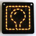
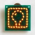
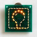
BlinkenArea ultimate logo board - "bulb" for short - is a small circuit board of 5x5cm showing the BlinkenArea logo with 42 LEDs. The orange LEDs display several animations using 16 brightness levels (gamma = 2.0). The board is powered by a single CR2032 button cell. | BlinkenArea ultimate logo board - "bulb" for short - is a small circuit board of 5x5cm showing the BlinkenArea logo with 42 LEDs. The orange LEDs display several animations using 16 brightness levels (gamma = 2.0). The board is powered by a single CR2032 button cell. | ||
This project is an extension of AntiKippenLights-Mini (which is a shrinked remade of AntiKippenLights). | This project is an extension of [[AntiKippenLights-Mini|AntiKippenLights-Mini]] (which is a shrinked remade of [[AntiKippenLights|AntiKippenLights]]). | ||
=== Downloads === | === Downloads === | ||
* [[: | * [http://git.blinkenarea.org/index.php?p=bulb BlinkenArea bulb GIT-Repository] | ||
* [[ | |||
* [[ | ==== 1.1.0 ==== | ||
* [[Media:Bulb-1.1.0.pdf|bulb manual 1.1.0 (PDF file)]] | |||
==== 1.0.0 ==== | |||
* [[Media:Bulb-electrics-1.0.0_2011-07-02.tar.bz2|electrics 1.0.0 (schematic, part list and layout)]] | |||
* [[Media:Bulb-firmware-1.0.0_2011-07-30.tar.bz2|firmware 1.0.0 (source code)]] | |||
* [[Media:Bulb-prog-1.0.0_2011-07-30.zip|firmware 1.0.0 (hex code)]] | |||
* [[Media:Bulb.pdf|bulb manual 1.0.0 (PDF file)]] | |||
=== Images === | === Images === | ||
<gallery> | <gallery> | ||
Image:Bulb-1.1.0.jpg|BlinkenArea ultimate logo board 1.1.0 | |||
Image:Bulb_full.jpg|BlinkenArea ultimate logo board - full on | Image:Bulb_full.jpg|BlinkenArea ultimate logo board - full on | ||
Image:Bulb_anim.jpg|BlinkenArea ultimate logo board - animation | Image:Bulb_anim.jpg|BlinkenArea ultimate logo board - animation | ||
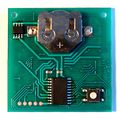
Image:Bulb_back.jpg|BlinkenArea ultimate logo board - back | Image:Bulb_back.jpg|BlinkenArea ultimate logo board - back | ||
</gallery> | </gallery> | ||
=== Instructions for assembling the kit 1.0.0 === | |||
# download the "electrics" package and unpack it | |||
# look at page 12 of "bulb.pcb.pdf" | |||
# solder the LEDs as seen in the PDF (the black dots next to the LEDs in the PDF indicate where the green dots on the actual LEDs have to be) | |||
# look at page 13 of "bulb.pcb.pdf" | |||
# solder the resistor (tiny, dark, with "1002" printed on it) to the position R1 (polarity does not mater) | |||
# solder the capacitor (tiny, brown, nothing printed on it) to the position C1 (polarity does not matter) | |||
# solder the FET (small black, 8 pins) to the position T1 (the dot on the actual part goes to the side with the half circle in the PDF) | |||
# solder the microcontroller (bigger, black, 20 pins) to the position IC1 (the dot on the actual part goes to the side with the half circle in the PDF) | |||
# solder the button to the position S1 (polarity does not matter) | |||
# solder the battery holder to the position B1 | |||
# insert the battery | |||
[[Category:Projects]] | [[Category:Projects]] | ||
Latest revision as of 21:39, 20 June 2019
| project overview | |
| |
| Year | 2011 |
| Number of pixels | 42 |
| Grayscales / Colors | 16 grayscales (gamma 2.0) |
| Illuminant | SMD LEDs |
| Power input | 120mW |
| Contact person | Stefan Schuermans |
| Project website | BlinkenArea bulb (en) |
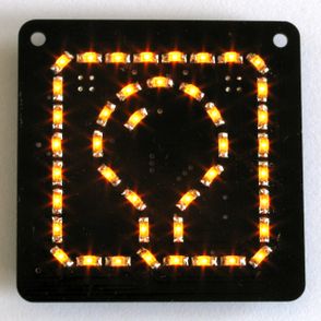
BlinkenArea ultimate logo board - "bulb" for short - is a small circuit board of 5x5cm showing the BlinkenArea logo with 42 LEDs. The orange LEDs display several animations using 16 brightness levels (gamma = 2.0). The board is powered by a single CR2032 button cell.
This project is an extension of AntiKippenLights-Mini (which is a shrinked remade of AntiKippenLights).
Downloads
1.1.0
1.0.0
- electrics 1.0.0 (schematic, part list and layout)
- firmware 1.0.0 (source code)
- firmware 1.0.0 (hex code)
- bulb manual 1.0.0 (PDF file)
Images
Instructions for assembling the kit 1.0.0
- download the "electrics" package and unpack it
- look at page 12 of "bulb.pcb.pdf"
- solder the LEDs as seen in the PDF (the black dots next to the LEDs in the PDF indicate where the green dots on the actual LEDs have to be)
- look at page 13 of "bulb.pcb.pdf"
- solder the resistor (tiny, dark, with "1002" printed on it) to the position R1 (polarity does not mater)
- solder the capacitor (tiny, brown, nothing printed on it) to the position C1 (polarity does not matter)
- solder the FET (small black, 8 pins) to the position T1 (the dot on the actual part goes to the side with the half circle in the PDF)
- solder the microcontroller (bigger, black, 20 pins) to the position IC1 (the dot on the actual part goes to the side with the half circle in the PDF)
- solder the button to the position S1 (polarity does not matter)
- solder the battery holder to the position B1
- insert the battery
