LogicLightsEnglish: Difference between revisions
ArneRossius (talk | contribs) (Created page with "__NOEDITSECTION__ {{Infobox |Name=LogicLights |Bild=Logiclights_test.jpg |Jahr=2018 |Pixel=144 |Farben=2 (on and off) |Leuchtmittel=5x5 mm LEDs (square) |Leistung= |Kontakt=Arne Rossius |Webseite= }} The '''LogicLights''' is a BlinkenLights clone without a microcontroller. The BlinkenMovies are stored in an EPROM, the rest of the circuit uses an NE556 and various logic ICs from the 74xx and 40xx series. Every frame require...") |
ArneRossius (talk | contribs) No edit summary |
||
| Line 1: | Line 1: | ||
__NOEDITSECTION__ | __NOEDITSECTION__ | ||
{{ | {{InfoboxEnglish | ||
|Name=LogicLights | |Name=LogicLights | ||
|Bild=Logiclights_test.jpg | |Bild=Logiclights_test.jpg | ||
Revision as of 17:56, 1 June 2024
| project overview | |

| |
| Year | 2018 |
| Number of pixels | 144 |
| Grayscales / Colors | 2 (on and off) |
| Illuminant | 5x5 mm LEDs (square) |
| Power input | |
| Contact person | Arne Rossius |
| Project website | |
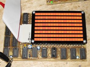
The LogicLights is a BlinkenLights clone without a microcontroller. The BlinkenMovies are stored in an EPROM, the rest of the circuit uses an NE556 and various logic ICs from the 74xx and 40xx series. Every frame requires 19 bytes in the EPROM: 18 for pixel data (one byte per column) and one byte for the display duration (in hundreths of a second).
Hardware
The circuit, including the LED matrix, is constructed on a Euro-size perfboard (160x100 mm).
The LED matrix is held together by several laser cut parts:
- base plate made from black, 3 mm thick PMMA ("Perspex") with narrow slots for the LED pins, so the LEDs can be mounted flat and straight,
- top plate with wide slots for 18 LEDs each (one row), also made from black 3 mm PMMA,
- vertical strips cut from black paper (80 g/m², like printer paper) which avoids the light from getting into neighbouring LEDs.
The many paper strips make it very fiddly to assemble the LED matrix. Cutting the paper strips also causes some problems, as the air flow inside the laser cutter can sometimes blow the finished strips from their locations, so they might be cut in half when the next strip is being cut.
- Schematic (PNG)
- Position of the components on the board (PNG)
Alignment
The animation speed can be varied with trimmer R33. To make the adjustment, jumper JP1 is removed and the frequency on the output of the oscillator (IC11 pin 5) is measured. Now, R33 is adjusted for a frequency of approx. 1800 Hz. If the EPROM is already programmed, the animation will flicker and run too slow during alignment, this is normal. Finally, jumper JP1 is installed again (pins shorted), the animation should now run at the correct speed.
Use
The animation will start to play at the first frame automatically as soon as the board is powered with a 5 V supply. When the end of the animation is reached, it will restart from the beginning without pause. If desired, the animation can be aborted and restarted with the push-button switch S1.
EPROM data format
Each frame requires 19 bytes in the EPROM. The first frame starts at address 0.
| Offset | Bytes | Content |
|---|---|---|
| 0 | 1 | Display duration in hundreths of a second (1 = 10 ms ... 255 = 2.55 s) |
| 1 | 18 | Pixel data, one byte per column starting from the left, MSB = bottom, inverted (0 = LED on, 1 = LED off) |
All frames are stored in sequence without gaps. After the last frame, a zero byte must follow to indicate the end of the animation.
Photos
More photos: http://arne.blinkenarea.org/LogicLights/.


