LightChaserRingEnglish
| project overview | |
| |
| Year | 2019/2020 |
| Number of pixels | 20/30 |
| Grayscales / Colors | |
| Illuminant | LED |
| Power input | 3V |
| Contact person | Arne Rossius |
| Project website | |
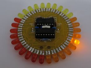
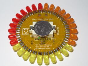
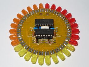
The Light Chaser Ring is the result of my attempts to design a light chaser which is as long as possible, using only two logic ICs and no other semiconductors. There are two versions: a 20 LED ring and a 30 LED ring.
20 LEDs
The 20 LED ring is the first version. It uses a decimal counter 74HC4017 and a quad NAND gate 74HC00, using two gates for an oscillator and the other two as a toggle flip flop.
The oscillator consists of IC2A, IC2B, R5 and C3. Usually this type of oscillator has an additional resistor for the input of the first gate (IC2A pin 1), but experiments determined that it still oscillates reliably without it. R5 and C3 set the frequency, although a much larger value for the capacitor should be avoided, owing to the "missing" resistor. The output of the oscillator provides the clock signal for the decimal counter IC1. This counter has 10 outputs, only one of which is active (high) at any time. At each clock pulse, the IC switches to the next output, jumping back to Q0 after reaching Q9.
IC2C and IC2D together with R1 to R4, C1 and C2 form a toggle flip flop. This type of flip flop toggles between its two states every time it receives a clock pulse. At any given time, one output is high and the other output is low. As the toggling happens at the negative edge of the input signal, the input is connected to Q9 so the flip flop changes state when the counter jumps from Q9 to Q0.
Two groups of 10 LEDs each are connected to the counter IC. The LED group connected to the low output of the flip flop is active; the LEDs in the other group have their cathodes driven high so they can't light.
A series resistor for the entire circuit limits the current through the LEDs. This means the LED's forward voltage, which is between 2 V and 3 V depending on colour (1.6 V for first-generation red LEDs), determines the supply voltage for the ICs. The ICs must be from a logic family which works down to a supply voltage of 2 V. The 74HC family is specified for a supply voltage between 2 V and 6 V.
Rev. 1.0
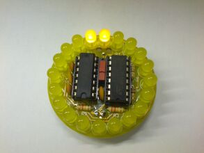
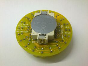
LEDs mounted axially (the usual way).
- Schematic (PNG)
- Schematic (EAGLE 4.x)
- PCB Layout (EAGLE 4.x)
- Construction Kit Instructions Rev. 1.0
Rev. 1.1
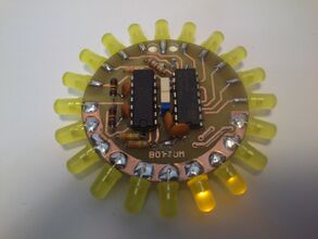
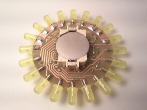
LEDs mounted radially on the edge of the PCB.
- Schematic (PNG)
- Schematic (EAGLE 4.x)
- PCB Layout (EAGLE 4.x)
- Construction Kit Instructions Rev. 1.1
The PCB layout of this variant is well suited for home-etching (see photo). The following should be taking into account:
- The layout should be printed directly from EAGLE. These settings result in mirrored prints for ironing onto or exposing the PCB:
- Top: Layers 1, 20, 116 and 201, Print settings: Black, Solid, Mirror.
- Bottom: Layers 16, 20, 116 and 216, Print settings: Black, Solid.
- 4 wire jumpers are necessary (along the thick traces between two vias, 2 on the top and two on the bottom side). Alternatively, the top and bottom pads of the vias can be connected by other means.
- Most components must be soldered from both sides due to the missing through-plating. As the pads under an IC socket can't be reached, the ICs have to be soldered without sockets.
30 LEDs
This version uses a different oscillator circuit which generates a sequence of 3 signals instead of the usual single signal. This way, the oscillator can light up 3 LEDs in sequence before advancing the decimal counter. This is called a ring oscillator, which is slowed down with R-C-circuits. Because it uses an odd number of inverters, there is no stable state and the oscillator always starts up. The capacitors are all discharged when power is first applied, and the oscillator will start oscillating at a few MHz, limited only by the propagation delay of the gates. The additional 10 kΩ resistor causes a slight imbalance, resulting in a sufficient imbalance in the charge in the capacitors after a few 100 ms so the oscillator slows down to its nominal frequency. This results in the effect that all the LEDs appear to light up for a short time after power-on, but actually they're lighting up in sequence with a very high frequency.
The oscillator doesn't work with some 74HC00 ICs. An IC made by ST in 1995 worked fine in my test setup, but TI-made ICs from current production (around 2020) resulted in high-frequency oscillations around the edges, causing the decimal counter to jump around almost at random. The problem can be solved by replacing the 74HC00 (NAND gates) with a 74HC132 (NAND gates with Schmitt trigger inputs). Due to the Schmitt trigger effect, the capacitors have to be charged further and the frequency drops significantly, but it can be increased again by reducing the value of the three 1 MΩ resistors if desired. The 3 resistors should all be the same value, otherwise some LED groups will light up longer than others. The same goes for the 3 capacitors.
Rev. 1.x
LEDs can be mounted axially or radially from either side.
- Schematic (PNG)
- Schematic (EAGLE 4.x)
- PCB Layout (EAGLE 4.x)
- Construction Kit Instructions Rev. 1.1, for PCB Rev. 1.1
- Construction Kit Instructions Rev. 1.0, for PCB Rev. 1.0 with a layout error
