BlinkenNumsEnglish
| project overview | |
| |
| Year | 2004 |
| Number of pixels | 160 (10x4x4) |
| Grayscales / Colors | 2 |
| Illuminant | LED Display |
| Power input | 5V/1A |
| Contact person | Arne Rossius |
| Project website | |
Introduction
In fact, I wanted to build something similar to BlinkenLights as my first BlinkenProject, but since I had an enormous amount of LED-displays from Pollin assortments I decided to get rid of those first. BlinkenNums consists of 16 seven-segment displays with 1.5 digits each (meaning one regular 7-segment digit and one that can only display a one and a minus sign in front) which are connected to 20 shift-registers of the type 74HC164 (10 segments per display, the decimal points and plus signs are not connected). It can be controlled by everything with at least 5 free CMOS-compatible outputs, e.g. an ATTiny controller or the PC's parallel port (possibly, a schmitt trigger for the clock signal is neccessary when using the parallel port).
Description
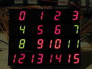
BlinkenNums consists of a matrix made from 4x4 seven-segment displays, each of whom can display numbers between -19 and +19.
Circuit
Buildup
The circuit consists of barely more than 74HC164 shift-registers and resistors. Because each display consists of 10 segments (minus, 2 for left digit, 7 for right digit), 5 shift-registers are neccessary for each line. As a result, the entire 4x4 matrix needs 20 ICs. The data inputs of each line is connected to different parallel port outputs, however, the clock inputs are all connected to the same pin. Up to two BlinkenNums can be controlled via parallel port or a microcontroller.
The circuit diagram only shows the circuit for one line, the other lines are exactly the same. The displays are split up into a 0.5- and a 1-digit one, which means that the pin numbers don't match the ones of the displays I used. The resistors for the displays must not be choosen too small as the ICs may not be loaded with more than 50mA (all outputs put together, may differ between manufacturers). With 8 outputs, the maximum current thus is 6.25mA per segment. I chose 560 Ohm resistors so the segment current is approx. 5.25mA.
Putting it together
The four individual lines are put together by connecting all clock and power supply (plus and ground) lines with each other. Don't interconnect the data lines! One schmitt-trigger (that's the thing with the transistors) is enough for all four clock lines. Depending on what the BlinkenNums will be connected to and how long the cable will be, the schmitt trigger might not be neccessary in some cases.
Physically, the 4 circuits are arranged on top of each other, so each circuit will provide a line of 4 displays.
Connection to the PC
The circuit can be connected to a PC's parallel port without trouble. In this case, the schmitt trigger should definitely be used, it didn't work without it on all the PCs I tried. The pinout for the parallel port is as follows:
| Parallelport Pin-Nr. | BlinkenNums-Anschluss |
|---|---|
| 1 | Clock |
| 2 | Daten, Zeile 1 |
| 3 | Daten, Zeile 2 |
| 4 | Daten, Zeile 3 |
| 5 | Daten, Zeile 4 |
| 18...25 | Masse (GND) |
As you can see, the data lines D4 to D7 are still unused, you could use them for a second BlinkenNums or build a double-sized BlinkenNums (provided you have or can write the appropriate software).
Construction log and photos
2004-07-15
A friend of mine has come to stay for a few dats and we decide to tackle the project. We order the missing parts (shift registers, resistors, IC sockets and a lot of wire) for two BlinkenNums from Reichelt and wait impatiently ;-).
2004-07-16
While waiting, the name "BlinkenNums" develops.
2004-07-17
Ordered two days ago and the parts already arrived! Finally we can start. Firstly, we soldered the displays and IC-sockets on two perfboards each, then the resistors leads were - using assembly-line-like work - bent, put into the boards, cut and soldered. In the evening, there was barely enough time left for the power supply connections.
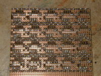
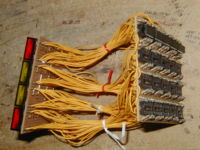
| The solder side with the solid power supply wires. |
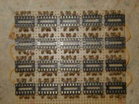
| The component side. |
2004-07-18
Unfortunately my friend had to go home already, so I'll have to continue by myself from now on.
2004-07-19
For the time being, I'll only complete one of the devices. Today I just soldered the connections for the clock and data lines of the shift registers as well as completed the power supply lines. I also took the first few photos.
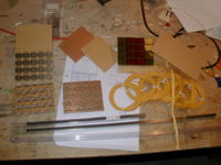
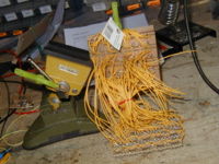
| The parts storage ;-) |
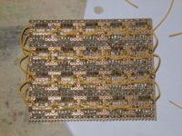
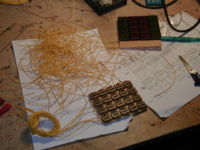
| The solder side with the new wires for clock and data of the shift registers. |
2004-07-21
Today the wires were soldered. In the evening I had completed half of them, the other half is just soldered to the display yet.
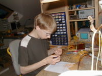
| Me cutting wires (you can't imagine a more boring work!) |
| All wires soldered on one side. Someone still keeping track of everything? ;-) |
| The first line during testing. |
| The first two line's wiring finished. |
2004-07-22
Done! After I connected all the wires and wrote a simple testing programme in Visual Basic, nothing worked at first :-(. The circuit only displayed nonsense. After a few hours of tireless programming and soldering as well as a test with manual control (using 4 regular and one debounced push-button), I discovered that obviously, the edges on the parallel port were not steep enough.
| It's not too easy to hold the circuit board at the right height while simultaneously trying to keep the other wires to fall where I need to solder and of course solder one of them. |
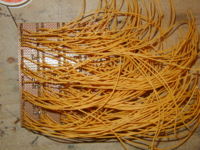
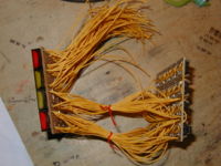
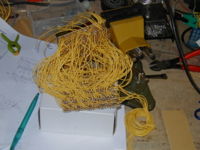
| Filally, all wires are soldered and bunched together. |
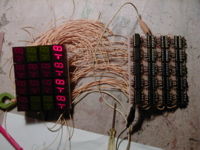
| The result of the first test (that's supposed to be numbers!) |
One schmitt-trigger later, at least the displays showed the same nonsense with each try, tough still not what they were supposed to show. A second analysis with oush-buttons resulted in the realisation that I wired up the segments in the wrong order. Fortunately, this could be resolved pretty easyly by reversing the order of the shift registers (though it was hard to reach the right spot with the soldering iron through all the wires).
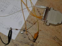
| The schmitt-trigger on the connector for the parallel port (knowing myself, this makeshift construction will stay that way for quite some time ;-)) |
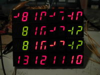
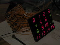
| The finished BlinkenNums: everything is working the way it should. |
The displays have to be controlled backwards, but it's easier to change the software than re-solder 160 wires ;-).
2004-11-26
After becoming a member of the BlinkenArea a few days ago, I finally found the time (and notion) to continue working on the second BlinkenNums. After I first had to clear up the table (there were still cut wires from the first BlinkenNums lying around as well as a lot of other stuff) and then my printer's ink catridge decided on leaking instead of printing the circuit diagram, I didn't manage to do more than cut the wires, connect the power-supply, data and clock lines and wire the first line. In addition, I started working on a control programme that'll run in DOS and is also capable of displaying letters.
| A few wires and the BlinkenNums-boards we populated four months ago. |
2004-11-27
Continued soldering right after getting up, listening to the /dev/radio-programme about blinking objects. Connected the finished BlinkenNums and added a connection for the second one (D-SUB 9) to the parallel port connector while I was at it. A lot of it worked on the first try, just a few characters in the third line behaved strangely. The problem, which I was alternately trying to find in the wiring, the ICs, the long wires and the software, resolved themselves as I added a another schmitt-trigger for the new BlinkenNums. But now the fourth line became wonky. Long story short, one of the clear-inputs wasn't connected and thus was sometimes high, sometimes low and the associated line did whatever it wanted to. When all was working, I tweaked the programme a bit and noticed that a P1/133 using QB 7.1 is a lot faster than a P3/500 using QBasic 1.1.
| Soldering wires. The new wires from Reichelt have a different consistency (they're softer) what prevents putting them through the perfboard's holes with insulation but they also stay where I bend them more compliantly so I seldom had to use the wires-stay-away-clamp. |
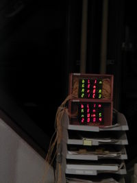
| The finished BlinkenNums on top of each other. In this picture you can see where the BlinkenNums will be displayed shortly: the 21C3, the 21st Chaos Communication Congress. |
