DuckEnglish: Difference between revisions
ArneRossius (talk | contribs) No edit summary |
ArneRossius (talk | contribs) No edit summary |
||
| (12 intermediate revisions by the same user not shown) | |||
| Line 1: | Line 1: | ||
{{ | {{InfoboxEnglish | ||
|Name=Duck | |Name=Duck | ||
|Bild=Duck.jpg | |Bild=Duck.jpg | ||
| Line 11: | Line 11: | ||
}} | }} | ||
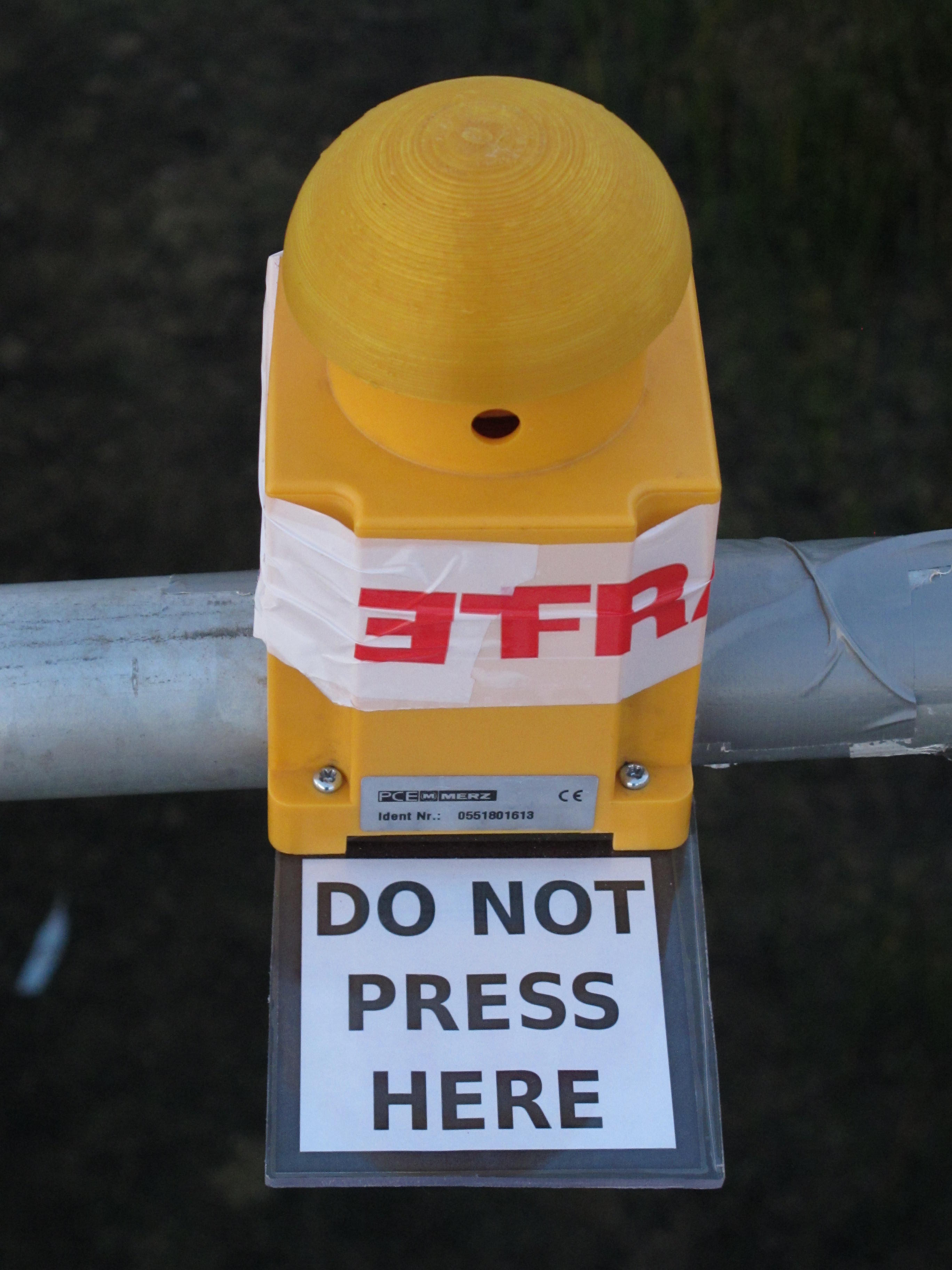
This '''Duck''' was inspired by the "duck" presented by the French Embassy on the | This '''Duck''' was inspired by the "duck" presented by the French Embassy on the camp [[OHM2013|Observe. Hack. Make. 2013]]. They installed a [http://arne.blinkenarea.org/OHM2013/0882%20Do%20not%20press%20here%20%28electronic%20duck%29.jpg big button labelled "Do not press here"], which played a loud duck quack when pressed. | ||
This version consists of 34 LEDs on a circuit board which are arranged in the shape of a duck and play varying animations. The button is located in one corner, the quacking sound is played back through a mini speaker on the PCB. | This version consists of 34 LEDs on a circuit board which are arranged in the shape of a duck and play varying animations. The button is located in one corner, the quacking sound is played back through a mini speaker on the PCB. | ||
== | == Variants == | ||
There are several variants of the Duck: | |||
* A 75% size version (prototype only). | |||
* A 50% size version, using 3 mm LEDs. | |||
* A 50% size version using SMD components - see [[DuckMiniEnglish|DuckMini]]. | |||
== Animations == | |||
Two PWM outputs are used for the speaker, with the second output generating the inverse PWM ratio to the first. In this way, the average voltage between the outputs is twice that of a single output to ground, increasing the volume. To get even more volume, two push-pull stages of two transistors each are used to amplify the AVR's PWM output signals because the internal | The animations are written in a special pseudo language created from assembly macros. The File "animations/ani_list.asm" specifies the order and number of repeats of the animations, while the comments at the beginning of the file explain the available pseudo commands that can be used to create animations. The other files in the "animations" directory are example animations. To create your own animation program, you can either enter all animation commands directly into the file "ani_list.asm" or create a separate file for each animation and then add them to "ani_list.asm" using the ".include" directive. | ||
== Audio == | |||
The sound to be played when the button is pressed is stored as a list of unsigned 8-bit values, i.e. the value 128 (0x80) is the zero level (silence). The value 0 must not be part of the audio data as it is used to detect the end of the list. The usable range of data values is thus 1 to 255 (128±127). The AVR is clocked at 8 MHz and uses an 8 bit PWM to generate the audio signal, which results in a sample rate of 31.25 kHz. | |||
To replace the quacking of the duck with a different sound, it must be converted into the described format (8 bits, unsigned, 31.25 kHz sample rate) which can be done with the program "Audacity". The same program can also be used to remove silence before and after the desired sound, as the memory for audio data is very limited. The program and the example animations together require a little over 1 KiB of program memory. This leaves just short of 7 KiB for audio data, which corresponds to an audio length of approx. 227 ms. After converting the audio data with Audacity, the perl script in the "audio" directory can be used to convert the raw audio file to an assembly file which must then be included in the main program file "duck.asm" (in the line immediately following the "audio:" label). | |||
== Version 1.0 == | |||
The circuit is controlled by an ATmega8 which multiplexes the LEDs and plays the quack sound when the button is pushed. The speaker is driven with PWM so no digital to analog converter is necessary. The data for the quack sound occupy approx. three quarters of the program memory, the rest is available for the program code and the animations. The project is powered from a 4.5-5 V supply, e.g. three AA batteries. | |||
Two PWM outputs are used for the speaker, with the second output generating the inverse PWM ratio to the first. In this way, the average voltage between the outputs is twice that of a single output to ground, increasing the volume. To get even more volume, two push-pull stages of two transistors each are used to amplify the AVR's PWM output signals because the internal resistance of the AVR outputs would limit the output current severely if the signals were used unamplified. | |||
The LEDs are connected in a traditional 6x6 matrix with the last two LEDs missing. The columns are directly connected to the AVR outputs without any current limiting resistors, leaving only the AVR's internal resistance of approx. 25 Ω to limit the current through the LEDs. The row ouptuts are amplified with NPN transistors to avoid fluctuations in brightness. | |||
=== Hardware === | |||
* [[:File:Duck-rev1.0-schematic.png|Schematic]] (PNG) | * [[:File:Duck-rev1.0-schematic.png|Schematic]] (PNG) | ||
| Line 28: | Line 47: | ||
* [[:Media:Duck-instructions-rev1.0.pdf|Construction Kit Instructions Rev. 1.0]] for PCB Rev. 1.0 | * [[:Media:Duck-instructions-rev1.0.pdf|Construction Kit Instructions Rev. 1.0]] for PCB Rev. 1.0 | ||
== | === Firmware === | ||
* [[:Media:Duck-20151215.zip|Firmware Version 2015-12-15]] | * [[:Media:Duck-20161204.zip|Firmware Version 2016-12-04]] for ATmega8 or ATmega8A | ||
* [[:Media:Duck-20151215.zip|Firmware Version 2015-12-15]] for ATmega8 or ATmega8A | |||
=== | === Always-on Mode === | ||
The | The always-on mode can be activated by placing a jumper between pins 4 (PB3) and 6 (ground) on the ISP pin header. In this mode, the duck turns on automatically when voltage is applied and can't be turned off with the button. To leave this mode, it is sufficient to remove the jumper. | ||
== Version 2.0 == | |||
In the second version, the controller was replaced with an ATtiny84, providing just 11 I/O-pins. The LEDs are now controlled with Charlieplexing, requiring only 7 pins. The transistors have been rewired to an emitter follower configuration, eliminating the need for base resistors and making the arrangement compatible with Charlieplexing. One column of LEDs is selected by driving the corresponding pin high, causing the transistor to supply the LED anodes with voltage, and the cathode pins for all LEDs in that column which should light up are driven low, while the remaining pins remain floating (set to input). This cycles through all 6 columns and repeats (like multiplexing). | |||
Currently, the only boards using this version are shrunk by 50% and use 3 mm LEDs. | |||
=== Hardware === | |||
==== 3 mm LEDs, 50% size ==== | |||
* [[:File:Duck-3mm-rev2.0-schematic.png|Schematic]] (PNG) | |||
* [[:Media:Duck-3mm-rev2.0.sch|Schematic]] (EAGLE 4.x) | |||
* [[:Media:Duck-3mm-rev2.0.brd|PCB Layout]] (EAGLE 4.x) | |||
* [[:Media:Duck-3mm-instructions-rev1.0.pdf|DUCK 3 mm Construction Kit Instructions Rev. 1.0]] for PCB Rev. 2.0 | |||
=== Firmware === | |||
* [[:Media:Duck-tn84-2022-07-25.zip|Firmware Version 2022-07-25]] for ATtiny84 or ATtiny84A | |||
=== Always-on Mode === | |||
In this version, the ISP pins are shared with the LEDs, so it's no longer possible to use a jumper. Instead, the always-on mode can be activated by holding down the button while power is applied. To exit this mode, power has to be turned off. | |||
== Photos == | == Photos == | ||
Latest revision as of 18:40, 1 March 2024
| project overview | |

| |
| Year | 2015 |
| Number of pixels | 34 |
| Grayscales / Colors | 8 grayscales |
| Illuminant | 5 mm LEDs |
| Power input | |
| Contact person | Arne Rossius |
| Project website | |
This Duck was inspired by the "duck" presented by the French Embassy on the camp Observe. Hack. Make. 2013. They installed a big button labelled "Do not press here", which played a loud duck quack when pressed.
This version consists of 34 LEDs on a circuit board which are arranged in the shape of a duck and play varying animations. The button is located in one corner, the quacking sound is played back through a mini speaker on the PCB.
Variants
There are several variants of the Duck:
- A 75% size version (prototype only).
- A 50% size version, using 3 mm LEDs.
- A 50% size version using SMD components - see DuckMini.
Animations
The animations are written in a special pseudo language created from assembly macros. The File "animations/ani_list.asm" specifies the order and number of repeats of the animations, while the comments at the beginning of the file explain the available pseudo commands that can be used to create animations. The other files in the "animations" directory are example animations. To create your own animation program, you can either enter all animation commands directly into the file "ani_list.asm" or create a separate file for each animation and then add them to "ani_list.asm" using the ".include" directive.
Audio
The sound to be played when the button is pressed is stored as a list of unsigned 8-bit values, i.e. the value 128 (0x80) is the zero level (silence). The value 0 must not be part of the audio data as it is used to detect the end of the list. The usable range of data values is thus 1 to 255 (128±127). The AVR is clocked at 8 MHz and uses an 8 bit PWM to generate the audio signal, which results in a sample rate of 31.25 kHz.
To replace the quacking of the duck with a different sound, it must be converted into the described format (8 bits, unsigned, 31.25 kHz sample rate) which can be done with the program "Audacity". The same program can also be used to remove silence before and after the desired sound, as the memory for audio data is very limited. The program and the example animations together require a little over 1 KiB of program memory. This leaves just short of 7 KiB for audio data, which corresponds to an audio length of approx. 227 ms. After converting the audio data with Audacity, the perl script in the "audio" directory can be used to convert the raw audio file to an assembly file which must then be included in the main program file "duck.asm" (in the line immediately following the "audio:" label).
Version 1.0
The circuit is controlled by an ATmega8 which multiplexes the LEDs and plays the quack sound when the button is pushed. The speaker is driven with PWM so no digital to analog converter is necessary. The data for the quack sound occupy approx. three quarters of the program memory, the rest is available for the program code and the animations. The project is powered from a 4.5-5 V supply, e.g. three AA batteries.
Two PWM outputs are used for the speaker, with the second output generating the inverse PWM ratio to the first. In this way, the average voltage between the outputs is twice that of a single output to ground, increasing the volume. To get even more volume, two push-pull stages of two transistors each are used to amplify the AVR's PWM output signals because the internal resistance of the AVR outputs would limit the output current severely if the signals were used unamplified.
The LEDs are connected in a traditional 6x6 matrix with the last two LEDs missing. The columns are directly connected to the AVR outputs without any current limiting resistors, leaving only the AVR's internal resistance of approx. 25 Ω to limit the current through the LEDs. The row ouptuts are amplified with NPN transistors to avoid fluctuations in brightness.
Hardware
- Schematic (PNG)
- Schematic (EAGLE 4.x)
- PCB Layout (EAGLE 4.x)
- Construction Kit Instructions Rev. 1.0 for PCB Rev. 1.0
Firmware
- Firmware Version 2016-12-04 for ATmega8 or ATmega8A
- Firmware Version 2015-12-15 for ATmega8 or ATmega8A
Always-on Mode
The always-on mode can be activated by placing a jumper between pins 4 (PB3) and 6 (ground) on the ISP pin header. In this mode, the duck turns on automatically when voltage is applied and can't be turned off with the button. To leave this mode, it is sufficient to remove the jumper.
Version 2.0
In the second version, the controller was replaced with an ATtiny84, providing just 11 I/O-pins. The LEDs are now controlled with Charlieplexing, requiring only 7 pins. The transistors have been rewired to an emitter follower configuration, eliminating the need for base resistors and making the arrangement compatible with Charlieplexing. One column of LEDs is selected by driving the corresponding pin high, causing the transistor to supply the LED anodes with voltage, and the cathode pins for all LEDs in that column which should light up are driven low, while the remaining pins remain floating (set to input). This cycles through all 6 columns and repeats (like multiplexing).
Currently, the only boards using this version are shrunk by 50% and use 3 mm LEDs.
Hardware
3 mm LEDs, 50% size
- Schematic (PNG)
- Schematic (EAGLE 4.x)
- PCB Layout (EAGLE 4.x)
- DUCK 3 mm Construction Kit Instructions Rev. 1.0 for PCB Rev. 2.0
Firmware
- Firmware Version 2022-07-25 for ATtiny84 or ATtiny84A
Always-on Mode
In this version, the ISP pins are shared with the LEDs, so it's no longer possible to use a jumper. Instead, the always-on mode can be activated by holding down the button while power is applied. To exit this mode, power has to be turned off.
Photos
More photos at http://arne.blinkenarea.org/Duck/gallery.htm.