MaxiBlink RGBEnglish
| project overview | |

| |
| Year | 2022 |
| Number of pixels | 24 |
| Grayscales / Colors | 7 (red, green, blue, yellow, cyan, pink, white) |
| Illuminant | 5mm RGB LEDs |
| Power input | |
| Contact person | Arne Rossius |
| Project website | |
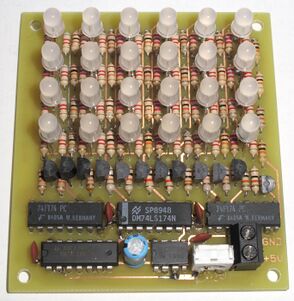
MaxiBlink RGB is the more colourful version of the MaxiBlink. It consists of a 4x6 LED matrix that lights up in seemingly random patterns and colours, controlled by a linear feedback shift register acting as a pseudo-random number generator.
Mode of Operation
MaxiBlink RGB is based on an 18 bit Maximum Length Sequence shift register with one row or column of the LED matrix connected to each flip-flop. Each row of LEDs has three "virtual columns", one for each colour. The rows are connected diagonally to prevent the patterns to be too "rectangular". A 555 oscillator is clocking the shift register chain. The circuit doesn't have a power-on reset, so if all flip-flop stages are set to "0" when powering on, the circuit won't start up and all LEDs will remain dark. As this appears to happen regularly with 74HC shift registers, the board can be modified to use the 4th XOR gate to invert one of the feedback taps, so now the circuit wouldn't start up if all flip-flop stages are set to "1", which doesn't appear to happen very often. In version 1.1, the circuit has been modified to include this mod.
Hardware
Version 1.0
- Schematic diagram (PNG)
- Schematic diagram (EAGLE 4.x)
- PCB layout (EAGLE 4.x)
- Kit instructions
- PCB modification instructions
Version 1.1
- Schematic diagram (PNG)
- Schematic diagram (EAGLE 4.x)
- PCB layout (EAGLE 4.x)
Enclosure
This is a design for a front cover, which can be 3D printed and screwed to the PCB. The LEDs stick out in the front through funnel-shaped holes. The effect looks particularly nice if the cover is printed with transparent or translucent material.
- Front cover (OpenSCAD code)
- Front cover (STL file)