DuckMiniEnglish: Difference between revisions
ArneRossius (talk | contribs) No edit summary |
ArneRossius (talk | contribs) No edit summary |
||
| Line 11: | Line 11: | ||
}} | }} | ||
The '''DuckMini''' is the <abbr title="Surface Mounted Devices">SMD</abbr> version of the <abbr title="Through Hole Technology">THT</abbr> [[DuckEnglish|Duck]]. The circuit and software are mostly identical | The '''DuckMini''' is the <abbr title="Surface Mounted Devices">SMD</abbr> version of the <abbr title="Through Hole Technology">THT</abbr> [[DuckEnglish|Duck]]. The circuit and software are mostly identical. More detailed information about the circuit and software can be found on the [[DuckEnglish|Duck project page]]. | ||
== | == Version 1.0 == | ||
The circuit is identical to the full-size duck except for the microcontroller. Instead of the loose battery holder for 3 AA cells, this version uses a soldered-down holder for 3 AAA cells on the bottom side of the PCB. It is recommended to also stick a piece of double-sided foam tape (mirror mounting tape) in the corner opposite the battery holder's pins. Above the battery holder, the PCB is just large enough to provide space for the large tantalum capacitor and an <abbr title="In-System Programming">ISP</abbr> pin header. | === Hardware === | ||
The circuit is identical to the full-size duck except for the microcontroller. For cost reasons, the ATmega8 microcontroller was replaced with an ATtiny88 which is only available in an SMD package. Instead of the loose battery holder for 3 AA cells, this version uses a soldered-down holder for 3 AAA cells on the bottom side of the PCB. It is recommended to also stick a piece of double-sided foam tape (mirror mounting tape) in the corner opposite the battery holder's pins. Above the battery holder, the PCB is just large enough to provide space for the large tantalum capacitor and an <abbr title="In-System Programming">ISP</abbr> pin header. | |||
Instead of using the large battery holder, the PCB also provides a footprint for a CR2032 button cell holder. Due to the lower voltage and the large internal resistance of the button cell, the quacking of the duck will be very quiet and the LEDs will be dimmer, but for a duck without sound which won't be turned on for days at a time, the button cell is still a good option. | Instead of using the large battery holder, the PCB also provides a footprint for a CR2032 button cell holder. Due to the lower voltage and the large internal resistance of the button cell, the quacking of the duck will be very quiet and the LEDs will be dimmer, but for a duck without sound which won't be turned on for days at a time, the button cell is still a good option. | ||
Revision as of 18:03, 3 January 2024
| project overview | |

| |
| Year | 2019 |
| Number of pixels | 34 |
| Grayscales / Colors | 8 grayscales |
| Illuminant | SMD LEDs |
| Power input | |
| Contact person | Arne Rossius |
| Project website | |
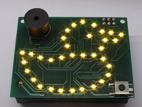
The DuckMini is the SMD version of the THT Duck. The circuit and software are mostly identical. More detailed information about the circuit and software can be found on the Duck project page.
Version 1.0
Hardware
The circuit is identical to the full-size duck except for the microcontroller. For cost reasons, the ATmega8 microcontroller was replaced with an ATtiny88 which is only available in an SMD package. Instead of the loose battery holder for 3 AA cells, this version uses a soldered-down holder for 3 AAA cells on the bottom side of the PCB. It is recommended to also stick a piece of double-sided foam tape (mirror mounting tape) in the corner opposite the battery holder's pins. Above the battery holder, the PCB is just large enough to provide space for the large tantalum capacitor and an ISP pin header.
Instead of using the large battery holder, the PCB also provides a footprint for a CR2032 button cell holder. Due to the lower voltage and the large internal resistance of the button cell, the quacking of the duck will be very quiet and the LEDs will be dimmer, but for a duck without sound which won't be turned on for days at a time, the button cell is still a good option.
Rev. 1.0
- Schematic (PNG)
- Schematic (EAGLE 4.x)
- PCB layout (EAGLE 4.x)
- Kit instructions Rev. 1.1 for PCB Rev 1.0
Software
Photos
More photos at http://arne.blinkenarea.org/duck-mini/gallery.htm.