DuckMiniEnglish: Difference between revisions
ArneRossius (talk | contribs) No edit summary |
ArneRossius (talk | contribs) No edit summary |
||
| Line 20: | Line 20: | ||
Instead of using the large battery holder, the PCB also provides a footprint for a CR2032 button cell holder. Due to the lower voltage and the large internal resistance of the button cell, the quacking of the duck will be very quiet and the LEDs will be dimmer, but for a duck without sound which won't be turned on for days at a time, the button cell is still a good option. | Instead of using the large battery holder, the PCB also provides a footprint for a CR2032 button cell holder. Due to the lower voltage and the large internal resistance of the button cell, the quacking of the duck will be very quiet and the LEDs will be dimmer, but for a duck without sound which won't be turned on for days at a time, the button cell is still a good option. | ||
* [[:File:DuckMini-rev1.0-schematic.png|Schematic]] (PNG) | * [[:File:DuckMini-rev1.0-schematic.png|Schematic]] (PNG) | ||
| Line 32: | Line 30: | ||
* [[:Media:DuckMini-20190501.zip|Firmware version 2019-05-01]] | * [[:Media:DuckMini-20190501.zip|Firmware version 2019-05-01]] | ||
== Version 2 == | == Version 2.0 == | ||
=== Hardware === | === Hardware === | ||
Revision as of 01:32, 24 February 2024
| project overview | |

| |
| Year | 2019 |
| Number of pixels | 34 |
| Grayscales / Colors | 8 grayscales |
| Illuminant | SMD LEDs |
| Power input | |
| Contact person | Arne Rossius |
| Project website | |
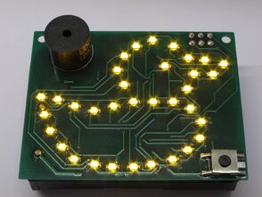
The DuckMini is the SMD version of the THT Duck. The circuit and software are mostly identical. More detailed information about the circuit and software can be found on the Duck project page.
Version 1.0
Hardware
The circuit is identical to the full-size duck except for the microcontroller. For cost reasons, the ATmega8 microcontroller was replaced with an ATtiny88 which is only available in an SMD package. Instead of the loose battery holder for 3 AA cells, this version uses a soldered-down holder for 3 AAA cells on the bottom side of the PCB. It is recommended to also stick a piece of double-sided foam tape (mirror mounting tape) in the corner opposite the battery holder's pins. Above the battery holder, the PCB is just large enough to provide space for the large tantalum capacitor and an ISP pin header.
Instead of using the large battery holder, the PCB also provides a footprint for a CR2032 button cell holder. Due to the lower voltage and the large internal resistance of the button cell, the quacking of the duck will be very quiet and the LEDs will be dimmer, but for a duck without sound which won't be turned on for days at a time, the button cell is still a good option.
- Schematic (PNG)
- Schematic (EAGLE 4.x)
- PCB layout (EAGLE 4.x)
- Kit instructions Rev. 1.1 for PCB Rev 1.0
Firmware
Version 2.0
Hardware
In version 2, the controller was replaced with a 14-pin type, either ATtiny84 or ATtiny804/814 can be used.
The LEDs are now controlled with Charlieplexing, requiring only 7 pins. The transistors have been rewired to a common collector configuration, eliminating the need for base resistors and making the arrangement compatible with Charlieplexing. One column of LEDs is selected by driving the corresponding pin high, causing the transistor to supply the LED anodes with voltage, and the cathode pins for all LEDs in that column which should light up are driven low, while the remaining pins remain floating (set to input). This cycles through all 6 columns and repeats (like multiplexing).
- Schematic (PNG)
- Schematic (EAGLE 4.x)
- PCB layout (EAGLE 4.x)
- Kit instructions Rev. 2.0 for PCB Rev 2.0
Firmware
As the ISP interface is sharing pins with the LEDs in this version, the always-on jumper as used in version 1 is no longer possible. Instead, the always-on mode can be activated by holding down the button while inserting the batteries. An automatic power-on when voltage is applied is not possible.
ATtiny804/814 don't support the ISP interface, so the 2x3 pin header becomes useless when using these controllers. In-system programming is still possible by soldering a wire to the unused pin 10 if the controller and connecting it to a UPDI programmer. Of course, ground also has to be connected to the programmer.
The PWM pins are different between ATtiny804/814 and ATtiny84. Pin 6 (PA7/OC0B on ATtiny84) can be set to the PWM signal WO0 with PORTMUX, requiring only a simple register setting at the beginning of the program. On pin 5 (PB2/OC0A on ATtiny84), no PWM signal is available. Instead, the CCL module is used to internally pass the WO1 signal through to LUT1-OUT, which in turn can be output on pin 5.
- Firmware version 2022-07-25 for ATtiny84
- Firmware version 2022-07-24 for ATtiny804 and ATtiny814
Photos
More photos at http://arne.blinkenarea.org/duck-mini/gallery.htm.