MBSEnglish: Difference between revisions
ArneRossius (talk | contribs) No edit summary |
m (copied pic from german page) |
||
| (One intermediate revision by the same user not shown) | |||
| Line 78: | Line 78: | ||
==== MBS online ==== | ==== MBS online ==== | ||
*[http://www.runningserver.com/?page=runningserver.content.thelab.mbs128 MBS128 by Dexter] | *[http://www.runningserver.com/?page=runningserver.content.thelab.mbs128 MBS128 by Dexter] | ||
*[http://s23.org/wiki/MBS More Pictures] | |||
*[http://s23.org/wiki/MBS | |||
<br> | <br> | ||
<br> | <br> | ||
| Line 85: | Line 84: | ||
[[Image:MBS Prototyp Detail big.jpg|300px]] | [[Image:MBS Prototyp Detail big.jpg|300px]] | ||
*Front view of the MBS: | |||
[[Image:MBS_front2.JPG|300px]] | |||
[[Category:Projects]] | [[Category:Projects]] | ||
Latest revision as of 21:30, 28 July 2015
| project overview | |

| |
| Year | 2007 |
| Number of pixels | 144 |
| Grayscales / Colors | |
| Illuminant | |
| Power input | |
| Contact person | Guido Pannenbecker |
| Project website | |
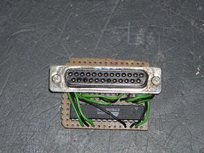
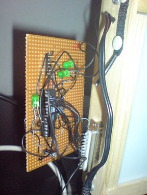
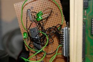
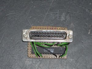
The MBS (MobileBlinkenServer) is a dongle which can for example be connected to BLP1.1 to deliver pictures. It only constists of a SUB-D plug for the connection to the BLP1.1 and an Atmega8. It is possible to realise the power supply by the BLP when adding VCC to pin 13 of the SUB plug by soldering a wire from VCC to pin 13 on the back of the BLP board. MBS can also be energised by an external cable.
The current version is able to repeat up to 387 frames (18x8, black-and-white), each with two Bytes wide time measurement in ms. The C-Tool Blinken2MBS changes any file format into fitting asm-Code by BlinkenLib. Image data is then copied behind the asm-Code and can be flashed by tavrasm, avrdude and a STK-200 on the Atmega.
The project is subject to GPL. No liability will be assumed for any damage or the like.
Download
Source code asm und c: MBS007.zip [11 KB]
Wiring scheme
The following link leads to the pin assignment Atmega8 which you can also get from the producer. The pin assingment of the SUB-D 25 can be found on this site: Pinbelegung SUB-D 25.
You can solder a compatible plug for the ISP or connect it to a further SUB-D plug to programm the Atmega (last column of the table).
| Pin at LPT-Kabel | Name at BlinkenLEDs | Pin at Atmega | Name at Atmega | Pin at ISP and name |
|---|---|---|---|---|
| 1 | column 17+18 | 26 | PC3 | - |
| 2 | column 1+2 | 2 | PD0 | - |
| 3 | column 3+4 | 3 | PD1 | - |
| 4 | column 5+6 | 4 | PD2 | - |
| 5 | column 7+8 | 5 | PD3 | - |
| 6 | column 9+10 | 17 | PB3 | MOSI - ISP Pin 4 |
| 7 | column 11+12 | 18 | PB4 | MISO - ISP Pin 5 |
| 8 | column 13+14 | 19 | PB5 | SCK - ISP Pin 2 |
| 9 | 15+16 | 25 | PC2 | - |
| 10 | unused (greyscales) | - | - | - |
| 11 | ? | - | - | - |
| 12 | ? | - | - | - |
| 13 | extra VCC (!) | 7, 20 | VCC | ISP Pin 1 + current for ISP |
| 14 | Clock | 27 | PC4 | - |
| 15 | open | 1 | /RESET | /RES - ISP Pin 3 |
| 16 | Strobe | 11 | PD5 | - |
| 17 | open | - | - | - |
| 18-25 | inertia | 8, 22 | GND | ISP Pin 6 + current for ISP |
Shifter
Something similar is already existing, the Shifter:
It can pass frames which are saved (only a few are possible) on the flash of a ATtiny2313 to BlinkenLEDs (with greyscales) or can receive and pass a MCUF stream serially.
Contact
Questions, problems, helpful suggestions or ideas are most welcome. Contact person is Guido Pannenbecker.
thx 2 Dexter, Arne, Sascha, Dirk and 1stein for hints, tricks and help. :)
MBS online
- MBS prototype detail:
- Front view of the MBS:


