LED-23English: Difference between revisions
(New page: __NOEDITSECTION__ {{Infobox-hw-en |Name = LED-23 |Jahr = 2007 |Pixel = 19 |Farben = red/yellow |Leuchtmittel = low current LED |Leistung = |Kontakt = ArneRossius |Son...) |
ArneRossius (talk | contribs) No edit summary |
||
| (8 intermediate revisions by 2 users not shown) | |||
| Line 1: | Line 1: | ||
__NOEDITSECTION__ | __NOEDITSECTION__ | ||
{{ | {{InfoboxEnglish | ||
| | |Name=LED-23 | ||
|Jahr = | |Bild=LED-23-03.jpg | ||
|Jahr = 2006 | |||
|Pixel = 19 | |Pixel = 19 | ||
|Farben = red/yellow | |Farben = red/yellow | ||
|Leuchtmittel = low current | |Leuchtmittel = low-current LEDs | ||
|Leistung = | |Leistung = | ||
|Kontakt = [[User:ArneRossius|ArneRossius]] | |Kontakt = [[User:ArneRossius|ArneRossius]] | ||
}} | }} | ||
=== | === Introduction === | ||
This little project was developed spontaneously, when somebody invited me to his 23th birthday party only two days in advance. I needed a nice present and due to the special meaning of the number 23, I decided to build this circuit. | |||
This | This circuit consists of an ATTiny11 microcontroller which shows different effects with 19 LEDs (unfortunately not 23 LEDs ;-)) composed as the number 23 and is operated by a 9V battery. Hence, the circuit could be kept small and can be put almost everywhere. | ||
=== | === Kits === | ||
Since [[24C3English|24C3]] LED-23 kits are available at the price of 10 Euros. They include the circuit board, all parts, a 9V battery and detailed instructions in english. If you are interested to get one, please get in touch with [[User:ArneRossius|Arne]]. The kit is appropriate for beginners and contains no SMD parts. | |||
=== Buildup === | |||
Despite the weird LED arrangement, the circuit can be built on a perfboard if you insert some LEDs vertically and others horizontally. Because there wasn't much room left with the LEDs all over the board, I had no choice but to use a small 8-pin AVR. I decided to use an ATTiny11 which has very little features but is sufficient for this circuit and very cheap. To control all the LEDs with just 5 output pins, I used a special multiplexing technique called "Charlieplexing" that uses the possibility to tri-state the outputs (switch to input without pullup). With this method, it is possible to control 20 LEDs, just enough for the 19 LEDs in this circuit. Unfortunately, the LEDs are a little darker than usual because of the multiplexing as the port-pins can't supply a lot of current. If you have enough time to buy some, get some low-current or high-efficiency LEDs, they'll light up bright with just a small current flowing through them. The LEDs become even brighter if you omit the diodes, as can be seen on the kit version schematic. At the time I built it, I wasn't sure that was going to work so I added them as a precaution. | |||
* [[:Image:Led-23.png| | I wired the perfboard with a very thin 0.09 mm² wire (about 30 AWG) for lack of space and because it looked better. It fits though the holes in the perfboard even with insulation so it was possible to continue passing the wire on the solder side in very tight spaces. Of course, a professionally made PCB would have been optimal, but there wasn't time. | ||
* [[:Image: | |||
The software allows for animations to repeat a number of times before continuing with the next one so every animation just needs to be stored once. This means the one kilobyte flash memory of the ATTiny11 is enough for a decent-length animation programme. For simplicity, I used seperate assembler files for each animation which are included into the main programme source. As every line must consist of an even number of bytes, there is a No-Operation-Command which is ignored when displaying the animation that can be used to fill lines with an odd number of bytes. Lastly there is a command that marks the end of the animation sequence so the programm knows when to jump back to the beginning of the first animation. In the version available for download below, all original animations are already included so you can use it without having to change it. | |||
* [[:Image:Led-23.png|Schematic (prototype)]] | |||
* [[:Image:LED23-kit-1.1-schematic.png|Schematic (kit version)]] | |||
* [[:Image:23leds_perfboard.png|LED composition for perfboard]] | |||
* [[:Image:Led-23.zip|assembler code and hexfile]] | * [[:Image:Led-23.zip|assembler code and hexfile]] | ||
* [[:Image:23creator.zip|software | * [[:Image:23creator.zip|software for creating animations (VB6 source code and Windows-EXE-file, might include some bugs!)]] | ||
=== Photos === | === Photos === | ||
{| border=0 | {| border=0 | ||
| [[Image:23_oben.jpg|left|200px]] | | [[Image:23_oben.jpg|left|200px]] | ||
| This is the top of the board with the 19 LEDs and the other parts | | This is the top of the board with the 19 LEDs and the other parts cramped between them. In consequence of not having enough LEDs of the same colour, the two digits are different colours ;-). | ||
|} | |} | ||
{| border=0 | {| border=0 | ||
| [[Image:23_unten.jpg|left|200px]] | | [[Image:23_unten.jpg|left|200px]] | ||
| | | Closely looking at the solder side, one of the two SMD capacitors can be seen between the soldering points of the voltage regulator (the other one is covered by the red wire). | ||
|} | |} | ||
{| border=0 | {| border=0 | ||
| [[Image:23_an.jpg|left|200px]] | | [[Image:23_an.jpg|left|200px]] | ||
| The 23 in use (the LEDs of the upper line | | The 23 in use (the LEDs of the three's upper line are not darker than the others but flashed up during exposure of the picture). | ||
|} | |||
{| border=0 | |||
| [[Image:23-bausatz.jpg|left|200px]] | |||
| The kit version with a professionally made PCB. | |||
|} | |} | ||
[[Category:Projects]] | |||
More photos: http://arne.blinkenarea.org/LED-23/. | |||
Latest revision as of 17:27, 28 December 2014
| project overview | |
| |
| Year | 2006 |
| Number of pixels | 19 |
| Grayscales / Colors | red/yellow |
| Illuminant | low-current LEDs |
| Power input | |
| Contact person | ArneRossius |
| Project website | |
Introduction
This little project was developed spontaneously, when somebody invited me to his 23th birthday party only two days in advance. I needed a nice present and due to the special meaning of the number 23, I decided to build this circuit.
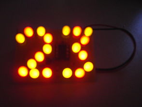
This circuit consists of an ATTiny11 microcontroller which shows different effects with 19 LEDs (unfortunately not 23 LEDs ;-)) composed as the number 23 and is operated by a 9V battery. Hence, the circuit could be kept small and can be put almost everywhere.
Kits
Since 24C3 LED-23 kits are available at the price of 10 Euros. They include the circuit board, all parts, a 9V battery and detailed instructions in english. If you are interested to get one, please get in touch with Arne. The kit is appropriate for beginners and contains no SMD parts.
Buildup
Despite the weird LED arrangement, the circuit can be built on a perfboard if you insert some LEDs vertically and others horizontally. Because there wasn't much room left with the LEDs all over the board, I had no choice but to use a small 8-pin AVR. I decided to use an ATTiny11 which has very little features but is sufficient for this circuit and very cheap. To control all the LEDs with just 5 output pins, I used a special multiplexing technique called "Charlieplexing" that uses the possibility to tri-state the outputs (switch to input without pullup). With this method, it is possible to control 20 LEDs, just enough for the 19 LEDs in this circuit. Unfortunately, the LEDs are a little darker than usual because of the multiplexing as the port-pins can't supply a lot of current. If you have enough time to buy some, get some low-current or high-efficiency LEDs, they'll light up bright with just a small current flowing through them. The LEDs become even brighter if you omit the diodes, as can be seen on the kit version schematic. At the time I built it, I wasn't sure that was going to work so I added them as a precaution.
I wired the perfboard with a very thin 0.09 mm² wire (about 30 AWG) for lack of space and because it looked better. It fits though the holes in the perfboard even with insulation so it was possible to continue passing the wire on the solder side in very tight spaces. Of course, a professionally made PCB would have been optimal, but there wasn't time.
The software allows for animations to repeat a number of times before continuing with the next one so every animation just needs to be stored once. This means the one kilobyte flash memory of the ATTiny11 is enough for a decent-length animation programme. For simplicity, I used seperate assembler files for each animation which are included into the main programme source. As every line must consist of an even number of bytes, there is a No-Operation-Command which is ignored when displaying the animation that can be used to fill lines with an odd number of bytes. Lastly there is a command that marks the end of the animation sequence so the programm knows when to jump back to the beginning of the first animation. In the version available for download below, all original animations are already included so you can use it without having to change it.
- Schematic (prototype)
- Schematic (kit version)
- LED composition for perfboard
- assembler code and hexfile
- software for creating animations (VB6 source code and Windows-EXE-file, might include some bugs!)
Photos
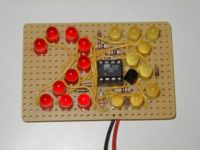
| This is the top of the board with the 19 LEDs and the other parts cramped between them. In consequence of not having enough LEDs of the same colour, the two digits are different colours ;-). |
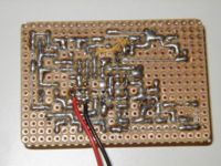
| Closely looking at the solder side, one of the two SMD capacitors can be seen between the soldering points of the voltage regulator (the other one is covered by the red wire). |
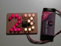
| The 23 in use (the LEDs of the three's upper line are not darker than the others but flashed up during exposure of the picture). |
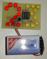
| The kit version with a professionally made PCB. |
More photos: http://arne.blinkenarea.org/LED-23/.
