ChaosknotenEnglish: Difference between revisions
From BlinkenArea Wiki
No edit summary |
No edit summary |
||
| Line 1: | Line 1: | ||
__NOEDITSECTION__ | __NOEDITSECTION__ | ||
{{ | {{InfoboxEnglish | ||
|Name=Chaosknoten | |Name=Chaosknoten | ||
|Bild=BlinkenArea-CCC-Chaosknoten_(front).jpg | |Bild=BlinkenArea-CCC-Chaosknoten_(front).jpg | ||
Revision as of 11:45, 21 June 2019
| project overview | |
| |
| Year | 2019 |
| Number of pixels | 42 |
| Grayscales / Colors | 16 Graustufen (gamma 2.0) |
| Illuminant | SMD LEDs |
| Power input | 120mW |
| Contact person | Stefan Schuermans, ST |
| Project website | BlinkenArea Chaosknoten |
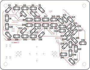
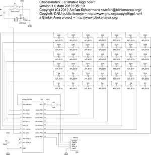
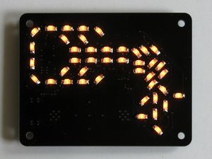
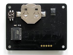
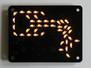
Chaosknoten - this is a small circuit board of 65 x 50mm, which uses 42 LEDs to show the official logo of logo of Chaos Computer Club. The orange LEDs display several animations using 16 brightness levels (gamma = 2.0). DThe board is powered by a single CR2032 button cell. On the backside there are two switches - one to turn it on and off, and the other one can be used to freeze the animation (freeze frame).
The logo is designed by Wau Holland. We are authorized by the Wau Holland Stiftung to provide this kit as long as we don't make any profit with it and we provide the layout information and software for free.
This project ist based on the bulb.
Downloads (firmware, layout, circuit layout)
Version 1.0.0
Images
- Chaosknoten-1.0.pdf öffnen
- Seite 1 und 2 aus "Chaosknoten-1.0.pdf" ansehen
- LEDs wie im PDF auf Seite 2 gezeichnet auflöten (Die schwarzen Punkte neben den LEDs im PDF zeigen an, wo die grünen Punkte der echten LED hingehören.)
- Seite 2 aus "Chaosknoten-1.0.pdf" ansehen
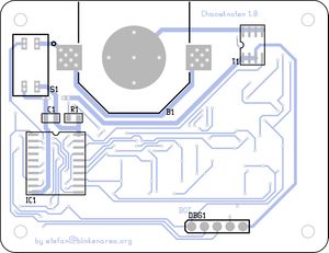
- Widerstand (winzig, dunkel, Aufdruck "1002") auf Position R1 einlöten (Polarität ist egal)
- Kondensator (winzig, braun, kein Aufdruck) auf Position C1 einlöten
- FET (klein, schawrz, 8 Pins) auf Position T1 einlöten (Der Punkt auf dem Chip gehört an die Seite, die im PDF mit dem Halbkreis gekennzeichnet ist.)
- Microcontroller (größer, schwarz, 20 Pins) auf Position IC1 einlöten (Der Punkt auf dem Chip gehört an die Seite, die im PDF mit dem Halbkreis gekennzeichnet ist.)
- Taster (scharz, zwei kleine weisse Hebel, 4 Pins) auf Position S1 einlöten. (der kleine Kringel markiert Pin 1. Pin 1 ist dort, wo die Zahl 1 aufgedruckt ist)
- Batteriehalter auf Position B1 einlöten
- Batterie einlegen
